Knowledge based hybrid model for
improving intelligent manufacturing system in rolling mils
Abstract
Hot steel plastic forming by rolling is amongst important industrial techniques because of huge amount of consumed resources, immense environmental impact, enormous quantity and significance of long products. Criteria for improving rolling operations include process efficacy, resource consumption, system reliability, product quality and ergo-ecological sustainability. There is an increasing availability of information at various levels of knowledge strata within and beyond the domain of forming by rolling. With the advances in the computerised information processing it becomes apparent that further progress is to be sought in intelligent combining strategies and theories developed in differing disciplines. Key to optimising this process is to be found in hybrid models. This approach calls for utilising cross-disciplinary knowledge, including suitable combination of selected methods such as stochastic, fuzzy and genetic modelling, process control and optimisation as well as supply chain and maintenance management. The partial results and evidence obtained by actual experiments such as the very-small-scale chemophysical modelling in laboratory rolling mill and knowledge-extraction from the industrial databases for rolling simple symmetrical products are presented. The further development is proposed on the basis of the knowledge-based hybrid model for improving the intelligent manufacturing system in rolling mills. Model structure and background algorithms are described along with the proposal for application to real industrial systems.
Keywords: manufacturing, rolling, knowledge-based, hybrid, modelling, optimisation.
1. Intro
Plastic forming long products by rolling (hereafter: “rolling”) is one of the most important and most efficient processes in the modern manufacturing. [1-5]. Hot steel rolling involves large-scale man-made systems that modify quality of an immense volume of solids and consume a proportional amount of resources. In particular, ergonomic issues and environmental sustainability (pollution and energy emissions) have become critical.
Numerous publications treat aspects of rolling, and a huge database is accumulated in the industrial systems. Yet even the limited review of literature [1-33] provides abundant evidence on the need for further optimising the rolling systems in-line with the philosophy of continuous improvements, and indeed in-line with the current calls for more rational use of global resources.
The global warming prompts for considering the changes in industrial patterns which will be significantly amplified by greenhouse gas emission constraints. Limits of technical systems will induce rationalisations in the production, distribution and consumption patterns. The concept of systems innovation and transitions to sustainability has increasingly gained attention over the past years.
Research that will address the above issues requires mobilising the sources which exceed capacity of a single academic discipline. A hybrid approach has better chances of bringing about prospective improvements.
A cross-disciplinary approach involving disciplines ranging from mechanical metallurgy and plastic forming of steels to the applied mathematical statistics and system control, has to be employed. Balanced collaboration across this spectrum will integrate various intelligent techniques with appropriate computational methods. While most of the approaches concentrate on a specialised-domain-knowledge, this approach builds on an idea that each specialty has something to offer and when combined they can provide more reliable solutions. A challenge is how to mobilise and integrate cross-disciplinary knowledge that combines suitable methods such as process modelling & control and operations optimization & scheduling. Merely collecting information is not sufficient for knowledge utilization. A synthesis is necessary along with comparative scrutiny of deduced and inferred conclusions. The information entropy increases and the intellectual synergy decreases with the degree of isolation. Coordinated utilisation of hybrid knowledge overcomes the limitations of isolated theories.
2. Problem description
The practice of hot forming of steel by rolling (“rolling”, hereafter) continues outstripping our theoretical understanding of it [5]. This means that expensive corrections and trials must be undertaken at the very costly industrial scale.
Various deterministic methods, such as finite element/difference modelling [6-9] and slip-line-fields [10] continue to be used in attempt to optimise the process within the deformation zone. These methods alone cannot provide sufficient shift in the optimisation effects; a combination with other “competing” approaches is needed. Similar approaches are already published [11], but still fall short of obtaining sufficiently optimised roll pass design implementations over a suitable time.
Concepts based on assumed or deterministically calculated values of variables such as friction coefficient and temperature do not provide sufficiently optimised dimensions for actual roll grooves. In this multi-pass process where most factors not only vary along the differing stages, but also fluctuate dynamically during the course of the continuous production series, it appears that a stochastic approach is a condition sine quo non.
Optimisation of rolling, providing that process is void of catastrophic interruptions (such as appearance of significant surface cracks, complete fractures or misguided workpiece), can be evaluated on the basis of the following indicators:
(i) yield
(ii) productivity
(iii) costs
(iv) reliability.
(i) The yield (output) of the rolling process can be classified as the percentage (%) of first class product, % second class and % of scrap.
(ii) The above output is achieved at the productivity rate of x products per hour.
(iii) In order to realise a rolling process, the certain amount of man-hours, volume of feed, quantity of cooling and lubricating media, quantity of the fuel and electrical energy, and certain quantity of tools, are required, which all present the production costs.
(iv) This is the probability that the above defined process will continue successful running until the time Tend is reached.
Ideally, hot solid steel should plastically flow through a sequence of passes in such way to maintain optimal level in all indicators. More detailed analysis of the factors influencing the above indicators leads to recognising further parameters, such as rolling pressure, temperature, rolling and sliding velocity and tool life. All these variables are significantly delimited by the phenomena embodied within so-called deformation (“plastic”) zone.
The following Fig 1 illustrates a roll pass for a most simple case of rolling a cuboid between two grooveless rolls:
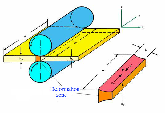
Fig 1: Grooveless (flat) rolling
The deformation (plastic) zone for the above simple case of flat rolling is characterised by changes in rolling pressure (p), friction (f), temperature (t), sliding distance (d) and sliding velocity (u) both in longitudinal and lateral direction. Values of p, f, t, and u differ for each of segments in longitudinal direction as indicated in Fig 2 showing the distribution of rolling pressure and sliding velocity.
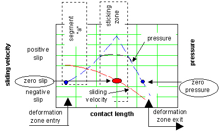
Fig 2: Distribution of the sliding velocity and pressure along the deformation zone
Qute disadvantageous variability occurs in the contact zone lateral direction as well.
Figure 3 illustrates changes in the coefficient of friction with the viscosity of interfacial media (due to variations in rolling temperature), involved velocities and rolling pressure
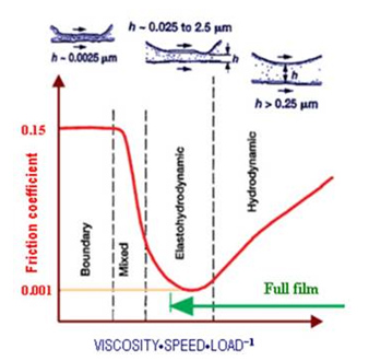
Fig 3: Change in the friction coefficient with viscosity, pressure and sliding speed (shown in logarithmic coordinates)
The lateral variability in factors p, f, t, u and d is especially emphasised in the case of calibre rolling. Next Figure 4 permits for understanding the causes for this lateral variability. The routes of the material flow departing from differing points along the calibre perimeter follow differing routes. This variety is further enhanced due to the differing lengths of the deformation zone corresponding to differing points along the calibre perimeter. Deformation zone is in particular complex in the case of calibre rolling with the presence of grooves cut in the surface of rolls.
Plastic flow of the rolled steel can be depicted by means of the following diagram conceptually illustrating two subsequent cross-sections of the rolled cylinder (Fig 4):
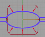
Fig 4: Schematic indicating steel flow during rolling the workpiece of a "rectangular" cross-section in an oval calibre
Red arrows in the above Fig 4 indicate flow of the perimeter points during the passage of the hot steel cuboid throughout an oval calibre. The following Figure 5 provides more views of this class of deformation zones:
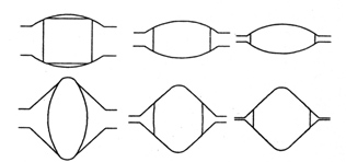
Fig 5: Typical cross-sections in the deformation zone formed by rolling solid cylinders in so-called oval and rhombic grooves [6]
At the onset of the rolling sequence, roll grooves are newly dressed and each calibre point has the same roughness. As the sequence of the rolled bars continues to pass through the same calibre, the geometry of the groove changes unevenly due to the uneven wear of the perimeter points, followed by an uneven change in the roughness of each segment of the calibre meridian, Fig 6.
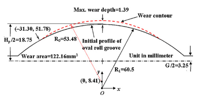
Fig 6: An example of wear contour in an oval pass [7]
The worn surface does not follow a smooth curve, partly due to the nonhomogenous structure of rolls, and partly due to the above lateral variations of rolling factors. This can be observed starting from the level of the roll microstructure, as shown in Fig 7.
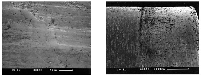
Fig 7: Worn surface produced by rolling-sliding contact of hot steel (900 oC) against the adamite roll [4]
In extreme cases, wear of the roll surface causes plastic ploughing at the points of critical wear, as shown in Fig 8. The same Figure shows an area damaged by the front end of the rolled bar.

Fig 8: Worn surface of the groove for rolling 200 UB section [4]
This change in the groove geometry, enhanced by the consequent changes in all corresponding variables, affects the flow pattern and the outcoming shape of the rolled steel. In the extreme cases, many adjustments along the rolling line (i.e. the production delays) are required in order to keep the final product within the geometric tolerances.
Roll maintenance requires periodic machining („re-dressing“) of roll surfaces to clean the worn layers and to recreate the initial geometry. This machining process reduces the roll diameter, and after several redressings this expensive tool has to be replaced by a completely new item. It should be noted that the amount of the diameter reduction during the cleaning of roll surface is determined by the point of extreme wear. Hence, the non-uniform wear that leads to the occurence of especially worn points is disadvantageous since it directly delimits the roll life.
Especially damaging is the presence of wear along the inclined groove sides shown in Figure 9.
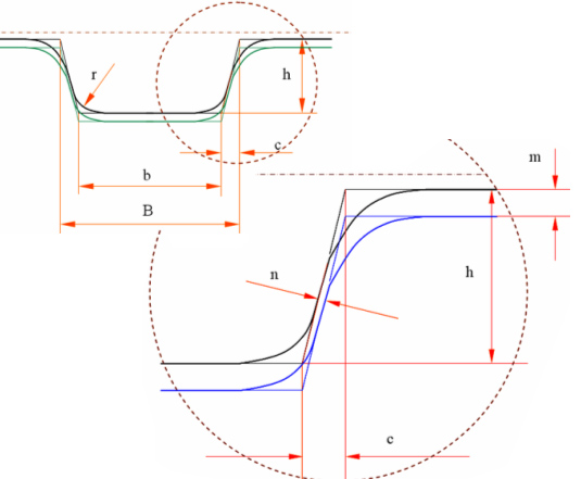
Figure 9: Typical box groove
Significant amount of „healthy“ roll material has to be cut off by means of the roll diameter decrease in order to regenerate the initial width defined by the dimensions „b“ and „B“ shown in Fig 9.
Roll wear significantly affects the key performance indicators and requires a detailed scrutiny. Roll pass design can significantly influence the future roll wear. Rolls can be machined (at the same costs) to generate quite differing groove geometries with significant consequences for both maintenance and operations. The roll geometry affects the metal flow inside the deformation zone (between the rolls), and has to be designed by taking in account the interaction of numerous factors, over the subsequent phases of a multistage process.
The most direct function of the rolls is to determine the geometry of the product. Rolls in a hot mill have to withstand severe variations of stresses and friction due to the contact with the steel having temperatures in the range of 900 to 1300 oC. In addition to the obvious need for resistance to breakage, there is the continuing component of roll wear that is critical to the economics of fabrication, and the geometrical tolerances of the products.
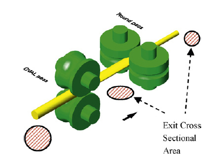
Rolls are plain (flat) or grooved (calibre rolls). Grooved rolls were introduced to improve the control of plastic flow of rolled steel, and their great flexibility for a variety of products has been proven especially in manufacturing steel sections. The main disadvantage of grooved rolls, apart from complications in their production and maintenance, is their significantly higher degradation when compared with plain rolls. This is associated with the non-uniform wear experienced, and also with the increased amount of radial machining required to regenerate calibre geometry. In an attempt to maintain simplicity in roll geometry, the complexity of rolling mills has been increased over the years, encouraging the development and application of diverse types of universal stands, including various combinations of horisontal and vertical rolls; an example is shown in Fig 10.
Fig 10: Schematic of deformation in round-to-oval-to-round groove rolling [7]
Significant knowledge concerning the deformation zone in plastic forming cuboids between flat rolls has been accumulated and broadened by an empirical progression to producing simple shapes such as “round” wire and rod, and further to rolling long products of complex cross sectional geometries. Rolling process is today organised on an immense industrial scale within the frame of sophisticated fabricating systems – rolling mills, Fig 11.
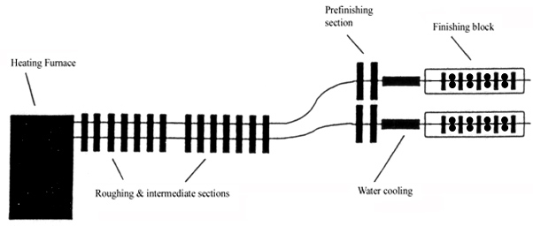
Fig 11: An example of a Rod Mill Layout (adjusted from [6])
Optimisation of these systems currently takes place only gradually, by means of tedious iterations and recursions, over the years of industrial production. Numerous existing computational models, however sophisticated, need to be significantly improved to achieve a shift to a radically more advanced level.
3. Preliminary results of partial research
Statistical analyses
Following the analogy with other complex processes, an assumption is made that extracting the advanced roll pass design knowledge can be done by means of appropriate statistical methods. To this end, roll passes must be defined in a suitable mathematical form.
In the case of rolling cuboids, the deformation zone is defined in two dimensions as shown in Figures 1 and 12, but the diagrams such as those shown in Figs 2 and 3 are needed to describe the variation of significant variables for this most simple case of a rolling pass.
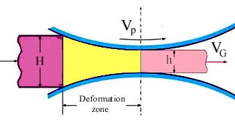
Fig 12: Deformation zone
The lateral dimension of the cuboid can be defined by a single scalar value, providing that width of the cuboid is much bigger than its height and larger than about 300 mm.
In the case of simple products with two or more planes of symmetry, the deformation zone is defined in two views, examples being shown in Fig 4-6, 9 and 13:
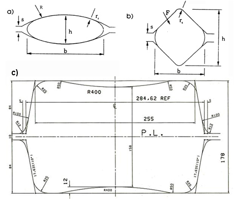
Fig 13: (a) oval groove, (b) rhombic (“diamond”) groove and c) box groove.
In order to evaluate likelihood of obtaining statistically significant correlation based on the roll pass geometry a mini-mill was used to experiment with hot rolling of round steel wire.
Mini mill consisted of two stands with grooveless (“flat”) horizontal rolls:
- No 1 stand (duo mill) with rolls Æ 260 mm
- No 2 stand (duo mill) with rolls Æ 160 mm.
Roll material: forged steel. Rolled material: plain carbon steel.
Entry wire dimensions (into No 1 Stand): 6 mm < D < 18 mm.
Entry temperatures: 1000 oC ± 10 oC.
Exit dimensions (out of No 2 stand): flat bar of thickness range 2 mm < H2 < 7 mm, and width-to-thickness ratio: 2 < (B2/H2) < 9.
Values of D, H1 and H2 are independent variables, i.e. these values can be selected before the rolling process is commenced.
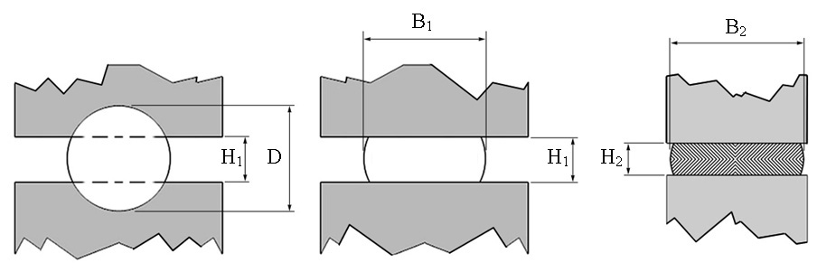
Fig 14: Rolling flat product from round wire
Sample size N = 300 bars.
Collected measurements allowed for evaluating the following correlations:
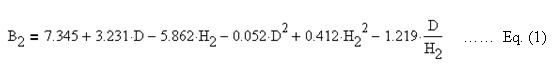
The above equation is valid providing that H1 (the roll gap) at the 1st Stand is set in accordance to the following equations:
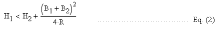
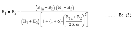
α = bite angle in radians
R = 0.5Æ; Æ = roll diameter (No 2 stand)
B1a = an assumed width at the No 1 stand exit. Iterations using Eq. (3) are repeated until the calculated B1 becomes sufficiently close to the assumed B1a.
In this example the regression coefficient R2 = 0.96 and the residual error is 0.35 mm. Equation (1) can be used for example to define the tolerances of the initial wire diameter, needed to obtain flat product within the dimensional specifications.
This pilot experiment indicates that regression analysis of roll pass geometry can provide quite reliable correlations, which in turn can be used for design & optimisations of the rolling process.
Further research should aim at regression analysis of more complicated geometries such as those shown in Fig 13.
Small-scale laboratory simulations using chemophysical models
Calculations and other computerised modelling still provide only approximate solutions to roll pass design. Further approximation can be achieved by chemo-physical simulations such as lead rolling at very-small-scale using laboratory rolling mill. Small-size laboratory rolling mills are used to roll special modelling materials such as lead and plasticine at room temperatures. [30-32]
Figures 15 and 16 show samples and full-size sections obtained during small-scale lead rolling and full-scale industrial rolling of more complex sections:
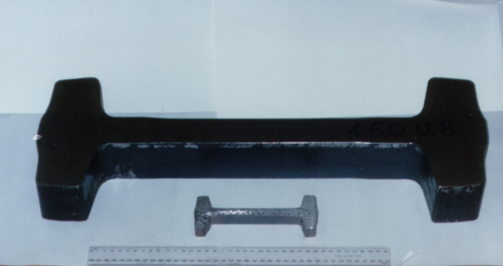
Fig 15: Full-scale sample and lead sample used to design hot rolling of a universal beam section
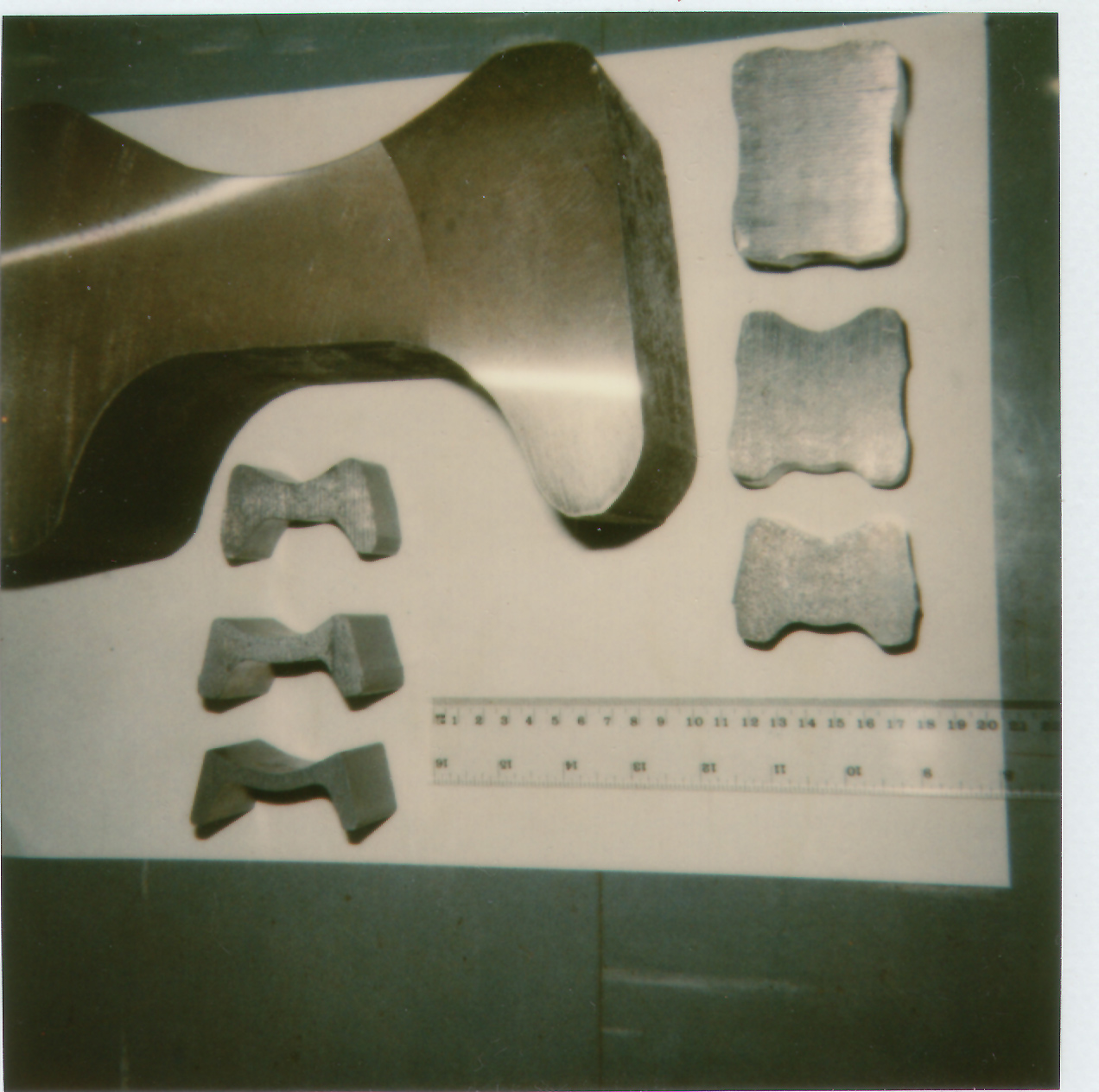
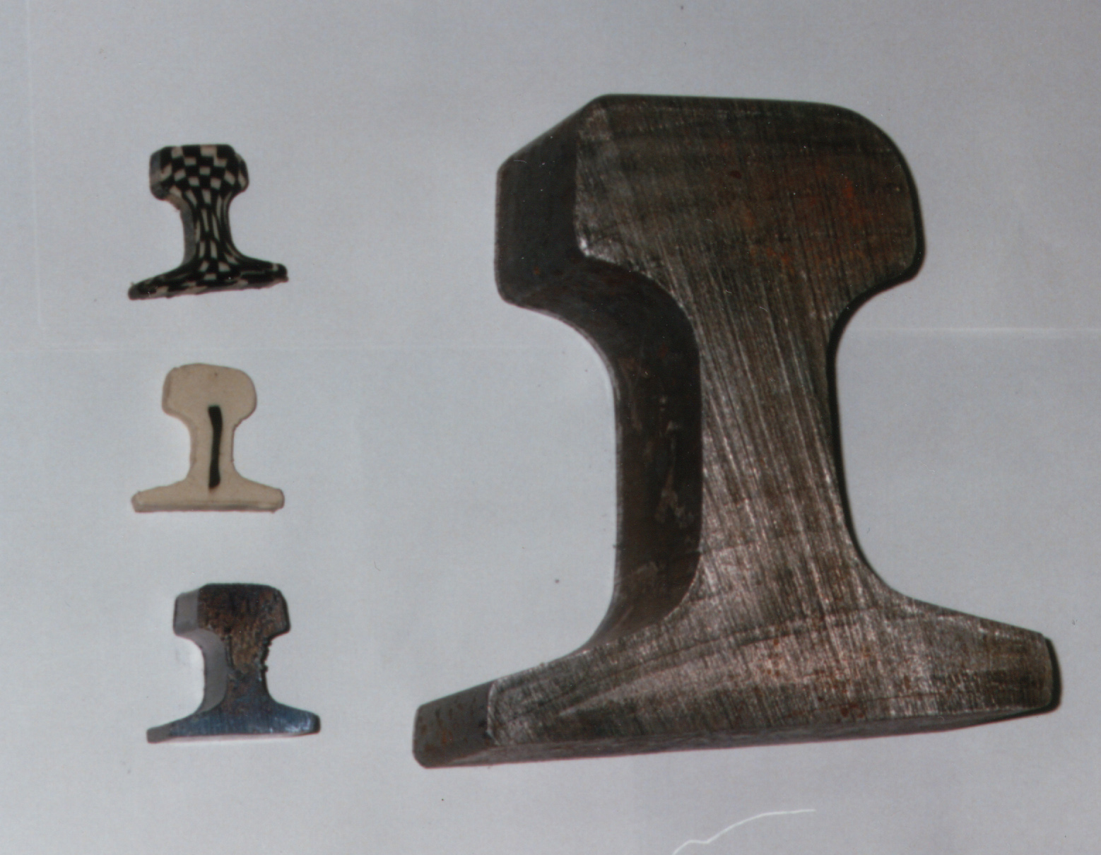
Fig 16: Full-scale samples obtained at an industrial hot rolling mill and laboratory samples obtained by rolling modelling materials at a small-scale rolling mill
A high degree of similarity was achieved in simulating the wide range of symmetrical and asymmetrical sections. The experimental facilities at the BHP Melbourne Research Laboratories were used to simulate hot steel rolling process. These facilities included small-scale rolling mills fully equipped with data acquisition system and were used for rolling either lead or plasticine as modelling materials at scales from 1:4 to 1:10th. Small-scale trials are used to test the satisfactory groove filling and load distribution in the rolling schedule (Fig 17 - 19).
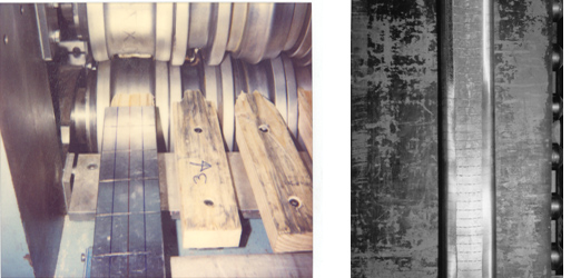
Fig 17: Lead rolling; grid is superimposed on the sample surface and after rolling used to determine the strains
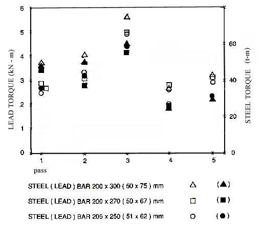
Fig 18: Comparison of torques obtained at experimental mill and in a full-scale rolling mill
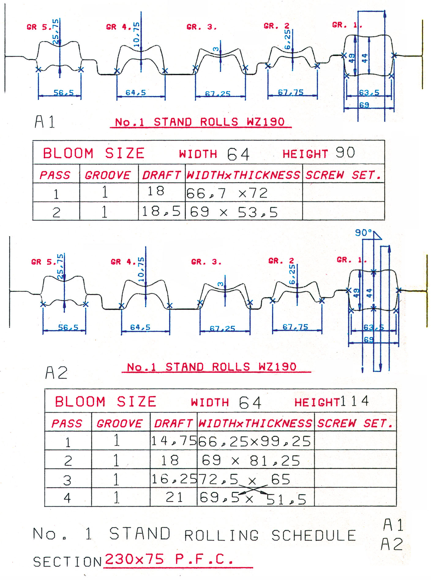
Fig 19: An example of the rolling schedule prepared for rolling lead in the experimental mill
Comparison of laboratory results with measurements in the industrial full-scale mill has been outstanding in terms of rolled geometry and loads.
Operations, control and maintenance systems
The contact zone between the rolled steel and the tools (rolls) is at the hearth of the rolling process. However, at an industrial scale, this process would be obsolete without the variety of supporting systems that enable operations, control and maintenance.
Computer control techniques for hot rolling mills have a history of successful implementations [12]. Automatic vision systems for on-line surface inspection are already used for high bar speeds. The commercial suppliers offer ultrasonic and eddy current systems, to detect defects in strip, plate, rod, bar, wire, tube and billet to 1200°C at high speeds.
The on-line set-up control ranges from controlling dimensions of the rolled bars along with the predicting temperatures and rolling loads via tension and speed control [13], and the microstructure and mechanical attributes control in the high speed continuous rod mills [6], to surface defect detection and identification, [14-18].
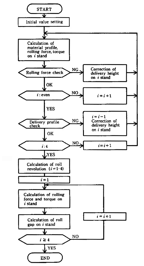
Fig 20: An example of calculation flow for on-line set-up control [12]
New statistical approach to defect detection and discrimination has been tried using the discrimination of true defects from random noise pixels by a dynamical threshold procedure. This method tracks the behaviour of clusters of selected pixels for varying threshold level. Boundary levels of the dynamic threshold range are determined from the estimated probability distribution of the pixel intensities. The method described here has been applied on a set of test images collected in an industrial steel mill for hot rolling. The results obtained in this test confirmed potential of this method for robust and reliable detection of scale roll-in defects. [14]
Roll wear norms [4]
The most useful wear control is not to register the final level of wear once the groove has been deemed unserviceable, but to monitor the wear rate on-line. For this an appropriate norm should be defined. A variety of norms are used to measure hot roll wear:
i) the mass of roll material removed during wear, ΔM,
ii) the volume of roll material worn out, ΔV, or
iii) the depth of the worn layer measured by the roll diameter decrease , ΔR = 0.5 ΔÆ,
each being usually related to the following variables:
a) the number of roll revolutions (N),
b) mass of the rolled product
c) length of the rolled product
d) contact time (t), and
e) sliding distance (L).
The suitability of the measure of wear is affected by the motives of investigation. For example, the use of ΔM would incorporate the effects of differences in density of roll materials on wear.
This analysis departs from the locus of the problem: the contact zone in rolling process. Assuming that no catastrophic damage (such as sudden fracture) of the tools occurs during rolling operations, the radial wear, ΔR, is of much concern. This term too can be defined in various ways. In real conditions met in the roll shop, ΔR describes the depth of the worn layer as the decrease in roll radius caused by both wear and by subsequent machining. The surface microstructure is affected by thermomechanical stresses and diffusion processes. Further factors are surface and subsurface micro and macro cracks. The amount of radial machining has to be increased (by factor of 3 to 4) to compensate for the above effects.
Wear rate, w, then can be defined as w = ΔR/L ……………. Eq. (5)
L = sliding distance of a point at the groove perimeter against the hot steel surface.
L = NsU/vp ....................................................................................................... Eq. (6)
N = total number of revolutions during the contact
U = | Vp - Vg | = sliding velocity
Vg = velocity of the rolled material
Vp = roll peripheral velocity
s = deformation zone arc length.
Figures 2 and 12 illustrates some variables included in Eq. (6). Considering that roll peripheral velocity vp is constant, it appears that (Vp - Vg) cannot be equal to zero along the whole interface “s” in the deformation zone. An idealised distribution of the sliding velocity U, along the deformation zone for rolling cuboids is shown in Fig 2. In the case of grooves shown in Fig’s 5, 9 and 13 the sliding velocity will vary in both lateral and longitudinal direction.
This can be taken in account by calculating the wear rate for each segment
wi = DR vp / si Ui ............................................................................................... Eq. (7)
In the longitudinal direction, for N contact-revolutions and the whole length of the deformation zone curve s, it holds:
However, for the lateral direction, the change in s (deformation zone length) must be taken in account as well. Problem of sliding in rolling continues to be investigated [19-23].
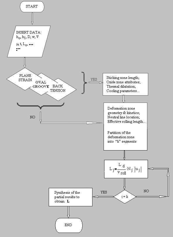
Fig 21: Flow chart for calculating the sliding distance during the rolling process [23]
4. Proposed further research
Current research into roll pass design, rolling operations and maintenance of rolls in hot rolling mills does not take sufficient advantage of information accumulated by the rolling mill operators and roll manufacturers. Industrial and scholarly classified databases can be analyzed using special hybrid approach that combines stochastic modeling with other modeling strategies and advanced metrological methods. Bearing in mind the criteria described in problem description, the minimum intent is to derive a model can be used as a decision support system for the roll pass (re)design which is optimisable by means of minimised corrections the during the operations and maintenance in an industrial hot rolling mill.
It is proposed to delimit this research to hot rolling of simple products which have three or more planes of symmetry.
Stage 1
As a first step, it is proposed to extract stochastic models of roll pass sequences, using the available databases. These models can be derived by combining the data obtained by scholarly published empirical algorithms for roll pass design, amalgamated with the measurements made available from real rolling mill.
Prerequisite for this is to transform roll pass design data into mathematical forms suitable for statistical analysis. This mathematical problem is most likely to be solved by a hybrid model combining stochastic approach with fuzzy or genetic algorithms (or both). Once this is achieved, knowledge about the roll pass design, which is now encoded in the competing and disconnected algorithms defined in scholarly publication and engineering documentations can be extracted and amalgamated, for example in the form of a series of regression functions.
For example, roll grooves can be translated into appropriate vectors. Generic functions can be used to enhance the analysis of a broad spectrum of pass geometries. Once this is achieved, statistical analysis of vector series can be conducted to extract the roll pass design correlations based on many observations of industrially realised rolling sequences.
This will enable intelligent anticipation of the roll pass design by means of identifying the limits of possible bands of pass geometries. Such information can be used to calibrate promising trials at commencement of new mills and/or profiles, to optimize existing schedules, to define emergency roll pass design routes, to modify real-time roll pressures to compensate for sudden or gradual changes in processing, etc.
Figure 22 illustrates one way of translating the information defined in Figure 13 (c) into vectors
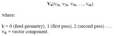
Groove meridian segments in Fig 22 are defined by a series of osculating curves. A generic function for osculating curve can be defined by generic expression shown in Eq. (9)
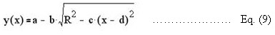
where: x and y are Cartesian coordinates of groove meridian segments a, b, c, d and R are parameters of the osculating segments.
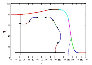
Fig 22: One way of translating the information defined in Figure 13 (c) into vectors
The following Fig 23 presents several samples of mathematical variations of the groove meridian segment with varying coefficients of Eq. (10):
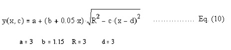
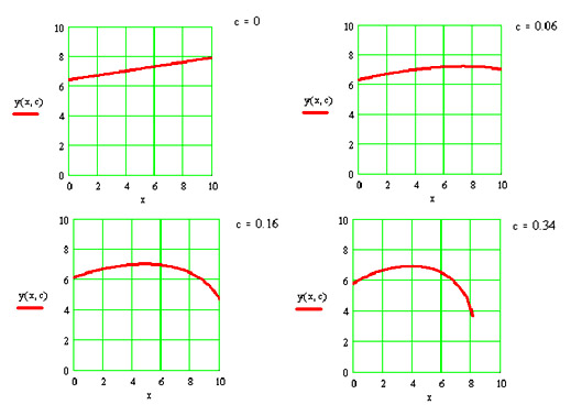
Fig 23: Variations of the groove meridian segment with the parameters of the Eq. (10)
For a "box" groove, there are 28 geometric vector components (7 osculating segments) plus 6 x-coordinates for 6 tangential points, which gives in total 34 components. For other calibres (such as diamond, round, oval) there is 16 geometric vector components (4 osculating segments) plus three x-coordinates for 3 tangential points, giving a total of 19 components. For each calibre there are additional components needed to complement vector specifications:
- Groove bottom roll diameter and the gap between the roll collars,
- Total number of passes, n,
- Order number of the pass starting with the initial cuboid N = 1, (hence the first pass calibre has the order number N = 2),
- Roll revolutions per minute, and
- Roll materials specification in terms of hardness and chemical composition.
To enable comparability between differing products, chemical composition of the rolled steel should be defined in terms of C, Mn, Si, Cr, etc. Also, the entry temperature of the feed before first pass should be defined.
Stage 2
Once the bands of the possible pass geometries are statistically defined, the advantage should be taken of chemo-physical simulations such as lead rolling at a very-small-scale using laboratory rolling mill. The extremes (maximum and minimum drafts and dimensions) should be experimentally verified, Fig 24.
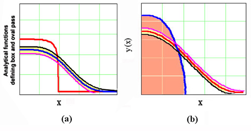
Fig. 24: Bands of possible groove geometries obtained by statistical analysis of roll passes
The widest bands are expected at the initial passes. If the laboratory rolling confirms that the extreme options can be successfully rolled, there is a justified high expectation that we can manoeuvre with selecting the roll pass options between these two limits.
Chemophysical simulations have been routinely used as an inexpensive method for laboratory testing of proposed design prior to conducting semi-industrial trials, Fig’s 19, 25 and 26.
Developing small-size simulations for processing special modeling materials should incorporate challenging tasks such as further decrease in the model size, new modeling blends and the small-scale roll materials that enable accelerated wear in laboratory rolling mill (such as the reinforced calcium sulphate “blackboard chalk”).
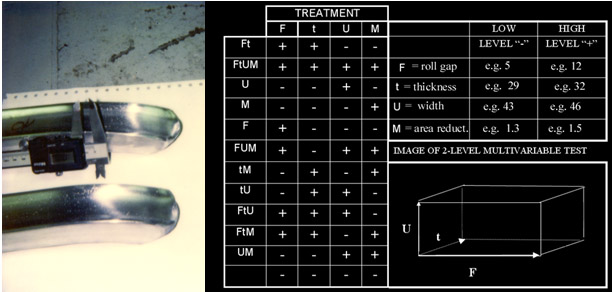
Fig 25: Statistical design of experiments applied to optimize laboratory rolling simulations [22]
It is important to realise the advantage of having achieved the highest reduction of the cross-section geometry at the early stage of rolling sequence. This is where the most intensive non-uniformity of the material flow should occur.
The consequences of the non-uniform flow can be indirectly observed on the shape of the bar ends (so-called "tongues") , Fig 26.
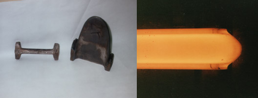
Fig 26: Front end (“tongue”) observed in simulation and in actual rolling mill
Tongue shape is initially affected by the degree of reduction from the feed geometry to begin to form the middle segment (“web”) of the bar. Reduction in early passes is by necessity much greater in the web formation area than the flange area. However in the later passes in both beams and channels the web becomes a virtually fully constrained flat under direct reduction so that almost all of reduction goes into elongation. At the same time the flange areas are undergoing indirect reduction with the capacity to spread, which means that elongation in these flange areas of the bar is comparatively greatly reduced. In later passes where the rolling temperature begins to be reduced, there is very little migration of material between web and flange at their junction. This means that the web continues to elongate whilst the flange tries to hold back this elongation, resulting in the tongue shape shown in Fig 26.
Tongue problem can be analysed using the small-scale laboratory rolling mills. The shape of the bar ends significantly affects both the roll bite and the risk of roll surface being damaged by an impact (see Fig 8).
Significant savings in the production duration can be achieved by increasing the draft at the initial passes. This draft is delimited by the maximum possible bite. However, the number of the initial passes and the risk of the impact damage can be decreased by re-designing the feed front edges. This potential can also be investigated using the simulation rolling of the model materials, such as lead at room temperatures.
Stage 3
Next stage is utilising/constructing a data acquisition system applicable to an actual hot rolling mill. Contemporary mills are increasingly equipped with the sophisticated measuring and control configurations usually linked with the operations control by virtue of computerised information processors. Challenge lies in combining this network within a hybrid model and complementing this system with additional sensors and measuring nodes.
Systemic approaches using intelligent search algorithms are already used to optimise rolling schedules, Fig 27 [11].
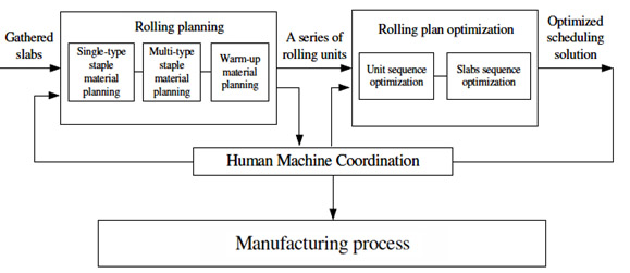
Fig 27: The structure chart of hot rolling scheduling system [11]
This hybrid model can be used to analyse the existing roll pass design database already applied in an actual hot rolling mill. This exposure will allow for tuning the roll pass design model defined within the stages 1 and 2, to fit the specific parameters that distinguish the observed process from other rolling mill plants. Here an emphasis is on linking the parameters of the rolling passes with other indicators of the process and quality control. Improving of the overall fabricating process must be embraced by the strategies such as non-linear and dynamic optimisation, supply chain, maintenance management and other methods of operations research.
This overall optimisation can be efficient only if the core of the process – the contact between the tools (rolls) and the rolled steel is optimised.
For example, one point is represented by designing the sophisticated pre-forming passes for the initial stages of the rolling process. Such a roll pass design conveniently influences operation parameters, attributes of product and the consumption of involved resources (man-hours needed for non-productive operations, tool life, energy consumption, etc).
Roll pass design which has satisfied criteria such as product quality and process productivity still has to satisfy the remaining criteria such as resource consumption, environmental & ergonomic sustainability and overall costs (e.g. the costs of the rolls). These criteria must be measured online and here is the role for innovative process control (such as automatic vision control).
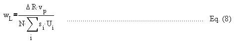
For example, in well designed tribosystems the stage of relatively constant wear rate extends over a significant span, before a stage of the rapid increase in wear rate takes place. One of the important roles of the control systems is to monitor this steady phase, and to signal any abrupt increase. However, it should be realised that the wear rate norm wL, which has been used at the roll pass design stage, is not applicable once the rolls are manufactured (machined or ground), and installed in the mill stands to be used in the production of specified product. Wear rate norm wL, defined by Eq. (8) is suitable only during the design stage, and for the comparison of performance of grooves in sample processes.
At the final stage, when decisions are made and the groves cut in the roll surface, and when the industrial production has been commenced, the wear rate should be measured using the norm wP

where
DRP = worn layer during the course of production, without taking in account the subsequent re-dressing, but only taking in account the change in the shape of the groove due to the contact with the rolled bar;
LP = the total length of the manufactured product (without the ends cut off) accumulated up to the point when DRP is measured.
By means of an online monitoring of wP, the ongoing process can be adjusted and the drafts can be modified along the series of passes to minimise the detrimental differences in wP observed at the differing grooves (the extreme local wear).
Traditionally, this is performed indirectly by controlling the final shape of the rolled product. In addition, the modern mills do have built-in sensors such as an online control of the temperatures, online measuring of the bar thickness at the intermediate rolling stages, measuring motor torque and roll separating force, vibration and a number of other condition monitoring methods.
A unifying hybrid model is sought for which will take in account a sufficient number of the above variables and factors and which will compute online optimisations based on the online monitoring of the total process. Rolling mills of the 21st century must focus on flexibility, productivity and quality. Many rolling mills work with the overall equipment effectiveness strategy and keep accurate control of downtime, gap time losses, speed losses, cobbles, nonconforming products and quality deviations [24]. Recent research efforts include modelling of hot strip rolling process using a hybrid neural network approach; It is claimed that this approach provides good prediction accuracy with very fast computing speed, Figures 28 and 29 [28].
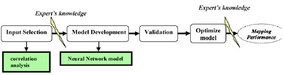
Fig 28: The general concept for the hybrid modelling is [28]
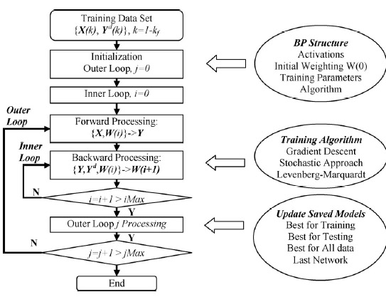
Fig 29: The neural network training algorithm [28]
Rolling mills readily use the continuous casting feed. This prompts for agile optimisation in order to avoid downstream bottlenecks. The overall problem is a specific case of hybrid flow scheduling problem accompanied by technical constraints of specific rolling mill. Since classic optimization methods fail to obtain an optimal solution for this problem over a realistic time, novel iterative algorithms have to be developed. They may be, for example, based on genetic algorithms or a combination of ant colony optimization and non-linear optimization methods, such as used in [25]. The capacity of this hybrid model will be empowered by the presence of stochastic model of roll pass design thus enabling more efficient on-line and off-line optimisation.
5. Conclusions
Anthropogenic consumption and harmful emission reductions requires major technological changes. The concept of systems innovation and transitions to sustainability has increasingly gained attention over the past years in academic and policy arenas. This prompts for considering radical changes in systems such as hot steel rolling mills. Steel manufacturing consumes enormous resources, for example the industrial water requirements include over 4 tonnes of water for 1 tonne of steel [26].
The proposed project offers sustainable improvement to strategically important industrial processes. The treated problem exceeds the capacity of a single academic discipline, and a cross-disciplinary approach involving fields such as mechanical metallurgy, plastic forming of steels, mathematical statistics, operations research and system control, has to be engaged. Hybrid amalgamation across this spectrum will integrate various intelligent techniques with appropriate computational methods. While most of the approaches concentrate on a specialised-domain-knowledge, this approach builds on an idea that each specialty has something to offer and when combined they can provide more reliable solutions. A challenge is how to mobilise and integrate cross-disciplinary knowledge that combines suitable methods such as process modelling & control and operations optimization & scheduling. Merely collecting information is not sufficient for knowledge utilization. A synthesis is necessary along with comparative scrutiny of derived and inferred conclusions. Accelerated use of hybrid knowledge is more effective compared to isolated theories which not take advantage of competing models.
Industrial and scholarly accumulated databases of rolling pass schedules can be analyzed statistically to extract stochastic models. The accumulated empirical and theoretical knowledge and the giant leaps in process control and information technology allow for further optimizing the hot rolling operations both off- and on-line.
A unifying hybrid model is sought for which will take in account a sufficient number of the variables and factors of the rolling process, and which will compute online optimisations based on the online monitoring of the total process. Rolling mills of the 21st century must focus on flexibility, productivity and quality. The expected benefits include the following:
- the rolling process will become more stable (more reliable); adjustment interventions will become less frequent and pass adjusting time will decrease,
- the depth of necessary redressing of rolls will decrease,
- overall life of rolls will increase,
- rolling process energy and other resource consumption will decrease due to more homogeneous flow of hot steel in the deformation zone,
- overall plant productivity and reliability will increase,
- overall yield of the manufacturing process will increase,
- production costs will decrease,
- working range for sequences and series of two-plane-symmetrical grooves will improve,
- the ecological and ergonomic sustainability of the overall process will improve.
References
[1] Spuzic S, O'Brien J, Stevens C "Basics of Manufacture", Multimedia publication, excerpts are published on the Internet in August 2008.
[2] S.Y. Yuan, L.W. Zhang, S.L. Liao, G.D. Jiang, Y.S. Yu, M. Qi “Simulation of deformation and temperature in multi-pass continuous rolling by three-dimensional FEM” Journal of Materials Processing Technology, Volume 209, Issue 6, 19 March 2009, Pages 2760-2766
[3] Spuzic S, Strafford K N, Subramanian C, Savage G (1994) "Wear of Hot Rolling Mill Rolls: An Overview", Wear, Volume 176, pages 261-271, 1994
[4] Spuzic, S., "Hot Rolling Mill Roll Wear - Some Aspects of High Temperature Abrasion", Ph.D Thesis, The
[5] W L Roberts “Hot Rolling of Steel” CRC Press, 1983
[6] I P Kemp, P D Hodgson, R E Gloss “Process and Microstructure Model of High Speed Rod Rolling” 1st Interational Conference on Modelling of Metal Rolling Processes 21-23 Sept. 1993, Imperial College, London UK
[7] S.M. Byon, D.H. Na, Y. Lee “Effect of roll gap adjustment on exit cross sectional shape in groove rolling—Experimental and FE analysis”, Journal of Materials Processing Technology, Volume 209, Issue 9, 1 May 2009, Pages 4465-4470
[8] S.Y. Yuan, L.W. Zhang, S.L. Liao, G.D. Jiang, Y.S. Yu, M. Qi “Simulation of deformation and temperature in multi-pass continuous rolling by three-dimensional FEM” Journal of Materials Processing Technology, Volume 209, Issue 6, 19 March 2009, Pages 2760-2766
[9] Hyuck-Cheol Kwon, Ho-Won Lee, Hak-Young Kim, Yong-Taek Im, Hae-Doo Park, Duk-Lak Lee “Surface wrinkle defect of carbon steel in the hot bar rolling process” Journal of Materials Processing Technology, Volume 209, Issue 9, 1 May 2009, Pages 4476-4483
[10] Kaj Klarin, Jean-Pierre Mouton, and Sven-Erik Lundberg “Application of computerized slip-line-field analysis for the calculation of the lever-arm coefficient in hot-rolling mills” Journal of Materials Processing Technology, 36 (1993) 427-446
[11] Jun Zhao, Wei Wang, Quanli Liu, Zhigang Wang, Peng Shi “A two-stage scheduling method for hot rolling and its application” Control Engineering Practice, Volume 17, Issue 6, June 2009, Pages 629-641
[12] K Baba, T Fujimoto, K Arai, K Fujioka, J Yamasaki, T Nakanishi “Development of Computer Control Techniques for Tandem Mill with Grooved Rolls”
[13] G. Li, F. Janabi-Sharifi “Fuzzy looperless tension control for hot strip rolling”
Fuzzy Sets and Systems, Volume 160, Issue 4, 16 February 2009, Pages 521-536
[14] Djukic D, Spuzic S (2007) “ Statistical discriminator of surface defects on hot rolled steel”; Proceedings of Image and Vision Computing New Zealand IVCNZ '07 Conference - 5-7 December 2007, Waikato University, Hamilton, New Zealand, pp 158-163
[15] T. Sugimoto, T,
[16] R.J. Montague, J. Watton, K.J. Brown "A machine vision measurement of slab camber in hot strip rolling", Journal of Materials Processing Technology 168 (2005) 172–180
[17] H. Jia, Y. L. Murphey, J. Shi, T.-S. Chang "An Intelligent Real-time Vision System for Surface Defect Detection", Proceedings of ICPR’04, IEEE Computer Society, 2004
[18] J. J. Haapamaki, S. M. Tamminen, J. J. Roning "Data mining methods in hot steel rolling for scale defect prediction". Proceedings of AIA 2005, Feb. 2005, pp 453-464
[19] Lundberg, S. K. and Gustafsson, T. (1994) "The Influence of rolling temperature on roll wear, investigated in a new high temperature test rig", Journal of Materials Processing Technology, Vol. 42, pp 239-291.
[20] Colas R, Ramirez J, Sandoval I, Morales J C and Leduc L A (1999) "Damage in Hot Rolling Work Rolls", Wear, Volume 230, No 1, May 1999, pp 56 - 60.
[21] Spuzic, S., Reid, I. and Zec, M. (1997) "Some Aspects of Interfacial Motion Relevant to Forced Oscillations", Fifth International Congress on Sound and Vibration, December 15-18,
[22] Spuzic, S., Zec, M., Abhary, K., Ghomashchi, R., and Reid,
[23] Spuzic S "An Algorithm for Rolling-Sliding Distance of Rotating Solids" International Workshop Vibration in Rotating Machinery, KFUPM University, Dhahran Saudi Arabia 29th April - 2 May 2000.
[24] C. Nord, B. Petterson, B. Johansson, “TPM—total productive maintenance
with experiences from Volvo”,
[25] Arezoo Atighehchian, MehdiBijari,HamedTarkesh “A novel hybrid algorithm for scheduling steel-making continuous casting production” Computers &Operations Research 36 (2009), pp 2450-2461
[26] Haughton G., Hunter C."Sustainable Cities" Routledge Taylor & Francis Group, 2003
[27] C. P. Burger and H. A. Gomide “Three-dimensional strains in rolled slabs by photoplastic simulation - a photoplastic model study of the strain fields that arise in the hot rolling of slabs of aluminium” Experimental Mechanics, Volume 22, Number 12 / December, 1982, p 441
[28] H. J. Kim, M. Mahfouf, Y. Y. Yang "Modelling of hot strip rolling process using a hybrid neural network approach", Journal of Materials Processing Technology, Volume 201/1–3 (2008), pp 101-105
Journal of Iron and Steel Research, International, Volume 14, Issue 4, July 2007, Pages 49-55, 60